Most building operators know they can set their HVAC system to a desired temperature – say, 24°C. But what really happens behind the scenes when you do that? Why doesn’t chilled water at 6°C feel that cold in your room? And how do components like VFDs and valve actuators work together – or against each other – to maintain comfort and save energy?
In this blog, we’ll break down the little-understood logic of HVAC automation, covering:
- What happens after the chiller sends water at 6 – 7°C
- Why you never feel 6°C in the room
- How VFDs on AHU fans and valve actuators respond to temperature
- Whether these systems work together or conflict
- Why setpoint control is more intelligent than you think
Let’s simplify the complexity of HVAC in a way your facility team will appreciate.
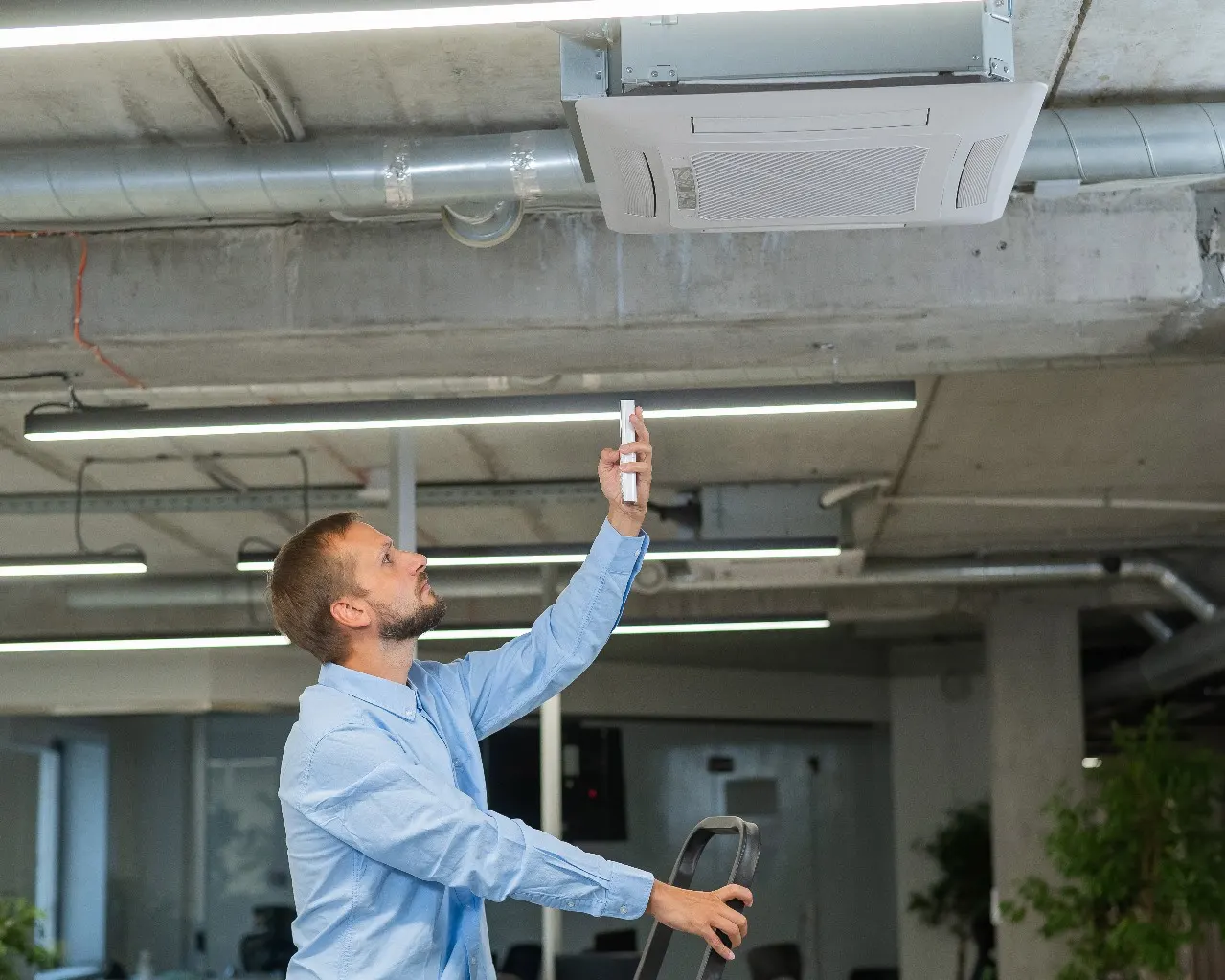 1. Chillers Cool Water, Not Rooms – That’s the AHU’s Job
In a typical water-cooled chiller system:
- Chilled water is produced at 6 – 7°C by the chiller
- This chilled water is pumped to the AHU
- The AHU uses a cooling coil to cool the air
- The cooled air is then blown into your space
But here’s the catch – you never feel 6°C air. That’s because the chilled water is only used to cool the air, and the air temperature you receive is usually 12 – 16°C, depending on the load, duct length, and insulation.
So, even though the water is very cold, the air you feel is moderated and comfortable – not freezing.
2. What Does the 24°C Setpoint Actually Control?
When you set the thermostat to 24°C, you’re not directly controlling the chiller or the AHU’s coil temperature. You’re simply telling the system:
“Keep the room at 24°C. Adjust cooling delivery to achieve that.”
This triggers the automation system to:
- Modulate chilled water flow via a valve actuator
- Adjust fan speed using a VFD (Variable Frequency Drive) on the AHU motor
- Balance both air volume and cooling intensity until the room temperature reaches your setpoint
It’s an intelligent feedback loop.
3. The Role of the Valve Actuator
A valve actuator is a motorized device that opens or closes a chilled water control valve.
- If the room is too warm, the actuator opens more, allowing more 6°C chilled water to enter the coil.
- If the room is near the setpoint, it partially closes.
- Once the desired temperature is achieved, the valve closes completely, stopping chilled water flow and saving energy.
This component essentially controls the cooling capacity of the AHU coil.
4. The Role of the VFD on the AHU Fan
A VFD controls the speed of the AHU fan motor.
- If cooling demand is high, the fan speeds up to circulate more cool air.
- As the room reaches the setpoint, the fan slows down, saving power.
- In some systems, the fan may even stop completely when cooling is not needed.
VFDs help with energy savings, reduce noise, and extend the life of the motor.
5. Do VFD and Valve Actuator Conflict or Work Together?
This is a common question. Since both devices respond to room temperature, are they fighting for control?
The answer: No, they work together – in sync.
- The actuator controls how much cold water is used for cooling.
- The VFD controls how much cool air is delivered into the room.
These two systems complement each other, not compete.
A central logic system (like SIOTA’s IoT platform or a BMS) ensures:
- If more cooling is needed, → valve opens + the fan speeds up
- If less cooling is neede,d → valve closes + fan slows down
- If the setpoint is achieved → both devices go into standby or minimum mode
This orchestration is what makes modern HVAC systems both smart and energy-efficient.
6. Putting It All Together: A Real-Time Example
Let’s say your room is currently at 26°C, and your setpoint is 24°C.
- The actuator opens, letting more chilled water into the AHU coil.
- The VFD increases fan speed, pushing more cool air into the room.
- As the temperature drops to 24°C, the system:
- Closes the valve gradually
- Reduces the fan speed
- Maintains the desired temperature without overcooling
All of this happens without human intervention. And that’s the power of coordinated HVAC automation.
Understanding how your chiller, AHU, actuator, and VFD interact is key to optimizing comfort, efficiency, and maintenance.
In a well-integrated setup:
- You don’t waste chilled water
- You don’t overrun your fans
- You don’t overload your chillers
- And you achieve consistent comfort with less energy
At SIOTA, we specialize in making these systems work together seamlessly – with real-time dashboards, automated alerts, and predictive logic that delivers savings you can see in your monthly reports.
Want to see how your building’s HVAC logic is performing today?
We offer a free control logic audit and simulation demo.
📞 9873270427
✉️ hina@siota.in
🌐 www.siota.in